Robot Localization
Updated: July 2024Introduction
Robot Localization is an incredibly important area of robotics that move around the surrounding environment. Understanding what is near the robot allows the robot to move and engage significantly easier.
Here, we will discuss the typical FIRST techniques using Limelight and PhotonVision to keep a robot oriented with the playfield. The conversation will revolve around what an April Tag is, and how it relates to pose estimation.
April Tag Background
April Tags use a clever algorithm to identify flat planes out in the world. It's a 4 step algorithm that breaks an image up into edges, segments, and eventually maps the squares to a pattern.
- Adaptive Threshold
- Segmentation
- Detect Quads
- Identify Tags
You can read whitepapers of the algorithm iteration approaches here:
- AprilTag: A robust and flexible visual fiducial system [2011]
- AprilTag 2: Efficient and robust fiducial detection [2016]
- Flexible Layouts for Fiducial Tags [2019]
Adaptive Threshold / Edges
This is a technique that looks at the average brightness of an image over a small surrounding region of the image. By looking at the nearby pixel values for brightness, the algorithm automatically scales up the magnitude of the edge based on its immediate environment. That is to say, a strong edge found on a black and white piece of paper will always evaluate to 1, even if it's in a dimly lit corner of the room with a pixel value of 188. It will evaluate the same way even if there was a light shining on the image, and the white pixel value was 255.
SegmentationThis is a lengthy iteration process based around thresholding, erosion/dilation (or shrinking/expanding), distance calculations, and more thresholding. You can see more of this in action with the OpenCV article on Watershed Analysis.
The goal is to identify consistent regions of an image, and their contours. Combining the edges from an Adaptive Threshold with segmentation, you can reliably pick out square shapes from various angles and orientations. This includes where vertices are located at the intersections of lines.
Detect Quads and Identify TagsLeveraging the edges and shapes, vertices and shape positions can be found. This allows the algorithm to convert the shape and position into a code that can be evaluated to a number. The blocks are not a binary representation of the number, but arranged in a specific way to make it easier to convert from tiles to digits while reducing ambiguities.
Limelight and PhotonVision
Limelights are somewhat of a Black Box. They has a decent library of documentation, but is still somewhat undocumented. Which, of course, is normal for paid products to have only basic documentation. They exist to do everything you will continue to read about in this article.
They run off of typical consumer grade hardware, recent models have run off of a Raspberry PI CM4 on a custom carrier board with a ~$25 CSI camera.
There is another open source competitor to Limelight called PhotonVision. It's an open source project with many of the same goals and features as Limelight. They are usually a cheaper solution, and feature accuracy/complexity trade offs. If there is someone versed in AI or signal processing, then PhotonVision may be a better solution for the team. Otherwise Limelights are highly functional out of the box and require little setup or tuning.
Of course, there is also a third option, of a completely inhouse solution. It's possible to build a full CV pipeline on top of NetworkTables from WPILib to run on a coprocessor, and OpenCV built for a RaspberryPI and cameras of your choosing. Or even an Nvidia Jetson embedded system using the same libraries, or Nvidia's VPI Library and using GPU Acceleration.
Limelight is the most popular for a reason, but it is not the only way to handle vision and pose calculations in FRC.
Calibration
Camera Calibrations are incredibly important, and usually handled during assembly during the QA process. None the less, during robot competitions, vibrations and damage will loosen components over time. This includes the alignment of camera lenses and chassis components. So lets talk about the major aspects of calibration.
Intrinsic Matrix
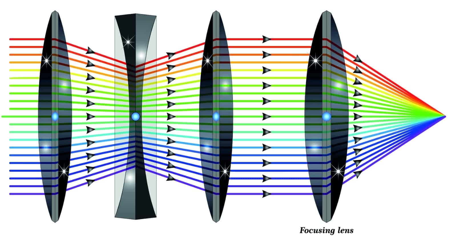
There are two major systems in a camera: the lens system, and the sensor array. In an ideal world, something called the optical axis will extend perpendicularly from the center of the sensor array and pass through the middle of every perfectly aligned lens. In the image above, every beam of light going through the lenses condense to a single point on the right hand side. This is where the sensor array exists. The curvature of the lenses exist to condense many rays of light into a single point to improve precision and signal quality of an observed image. This is a field called Geometric Optics. Geometric Optics also addresses other issues with lens error like
In reality, small microdefects and errors accumulate and cause the alignment to be off. This is solved with something called an intrinsic matrix. It describes the distortion of the image frame onto the sensor array. If you want a deep dive into the matrices that go into this, there is a good article by Kyle Simek that shows diagrams and the math.
One thing you might wonder about, seeing that there's an intrinsic matrix, might there also be an extrinsic matrix? There is! It's the orientation of the camera in the world space. This is also called the View Matrix, which you can read more in the article about procedural crop.
Radial Distortion

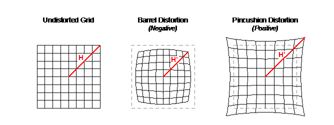
While the former section was about translational and skew distortions, there is also the chance for radial distortion over the surface of the lens. There are several types, however the most common distortion with these simpler cameras is barrel distortion which causes straight lines to bend outwards. The image above is an example of that.
ChArUco Board
So how do we keep a camera calibrated on the field? Typically with ChArUco boards, but a chessboard also works. ChArUco boards are chess boards with april tags inserted into them. This allows for the camera calibration process to collect not just the grid lines, but also the board's orientation.
Before matches, you can take a series of calibration snapshots and re-run the calibration calculations. This is relatively quick, only a minute or so, and the more images you can fit into the calibration check, the better!
Both Limelight and PhotonVision have articles on checking the calibration of a camera on the fly.
Sensor Integration
Typically, CV pipelines can only function on the incoming signal data. But that's only part of the story. Robot localization is done best as a multi-modal model. This means that additional sensor data can provide a more accurate and stable understanding of the robot's location and orientation. There are many froms of sensor data, but we are going to look at 3, which typically form something called an IMU, or Inertial Measurement Unit. This is a "fun" phrase to mean that the device tracks its movement over short distances.
Gyro
The first, and probably most likely component to be on your robot is a gyro. Not the edible greek wrap, your gyro is likely 0 initialized and will always start off facing "forwards", even if forwards is completely backwards in reality! This is where the benefits of a robust multi-modal localization system comes into play. The vision system will inform the gyro what direction is the initial orientation at startup, and the two systems will improve eachother's accuracy over time.
Note: Your Gyro may actually include other components within it, like those mentioned below. Please pay attention to its documentation!
The gyro may or may not be built into the camera system itself. Limelights are not built with a Gyro on board, but a RoboRIO can send any other Gyro data back to the Limelight when using their MegaTag2 pipeline. PhotonVision does not include a gyro signal input, and can only integrate the vision pose with the gyro on the RIO.
Custom pipeline enthusiasts rejoice! By using something like a sense hat with a Raspberry PI, or an ultra low power IMU for Nvidia Jetsons you can incorporate this sensor directly into your pose calculations. This can help handle motion blur, and improve pose quality before ever going back to the RIO.
Accelerometer
Accelerometers are usually a sibling component of a gyro, and they describe acceleration. Similarly, Limelights and PhotonVision don't have accelerometers on board, but the intrepid vision specialist can certainly include this on their coprocessor as well. Including an accelerometer into the pipeline will help deal with motion blur, and projecting the pose forward in time.
Magnetometer
Finally, the magnetometer is the classic compass you think about. It's the needle that detects north, which means that while the other two components detect motion, this one detects rotational position. Again, this isn't on a Limelight or supported by PhotonVision, but the adventurous among you can still incoporate it into your vision pipelines. Doing so helps with image rectification before processing. This, while unlikely, happens when robots get knocked over, or with control schemes that need to understand what "forward" actually means. Tight calibration and alignment at startup between the compass and the vision pipeline is necessary for the two to stay in agreement overtime.
Pose Estimation
This section is mostly for those who are trying to develop their own pipeline, and want to know what sort of math goes on, and how to leverage OpenCV to get that work done. Work will be filled in at a later date.
Linear Algebra
Trig
IMU
Pose Feedback Loop
Latency Gotcha
One important thing to keep in mind, is that your coprocessor handling vision pose estimations isn't aligned with the timestamps of the RIO. Any time there are two independent systems running, there will be an issue of latency. Latency causes problems for control systems, and it's important to include any latency values in pose estimations.
The WPILib pose estimator has a memory structure built into it, that lasts for a reasonably long amount of time. Both Limelight and PhotonVision currently use something called NetworkTables4 to keep these timestamps aligned, but those making their own pipelines need to be careful, or they will introduce desynced data into their robot and cause problems during motion.
Stereo Imagery
This is an extension of the custom pipeline mathematics in the Pose Estimation section. Information will be filled in at a later point.
Rectifying
Continuous Alignment